Using a 100 MHz, 16-channel, USB Logic Analyzer to eavesdrop on the Lego NXT brick’s I2C bus
This tutorial shows how to use the 100 MHz, 16-channel, USB Logic Analyzer developed by Saleae. Here, we are going to eavesdrop on I2C communication between a Lego Mindstorms NXT intelligent brick and an NXT ultrasonic sensor. This NXT ultrasonic sensor is supplied as standard with the Lego Mindstorms NXT robotics kit.
Owing to its very technical nature, this article is primarily aimed at those having some skills in electronics.
So, without further ado, let’s dive into the wondrous world of electronic communications using I2C.
First of all, what is I2C?
For those who don’t yet know, I2C is a communication bus developed by Philips in 1982, now a highly popular communications standard. It is therefore not surprising that Lego chose to use it in its NXT intelligent brick. All communications between the Lego Mindstorms NXT intelligent brick and sensors are carried out using the I2C protocol (communication with motors uses PWM, not I2C). A good understanding of I2C is therefore essential for robotics engineers versed in electronics who would like to design their own sensors, or connect their own circuits to the Lego Mindstorms NXT robot.
I2C is a half-duplex, bi-directional, synchronous, serial data bus. It makes simple and efficient communication possible between a microcontroller and one or more actuators or sensors. Without going into too much detail, but without omitting any important points either to ensure you can all build your own sensors, we will be looking here at the basics of I2C communication during a dialogue between our brick and these actuators.
How the I2C protocol works in master-slave mode
An I2C conversation works on the master-slave principle. In an I2C transaction between the NXT brick and its sensors, the NXT brick is necessarily the master and the sensors are necessarily slaves (even if technologically speaking they are able to act as masters), i.e. the establishment of any communication between the NXT brick and its sensors must always result from a request made by the brick.
The diagram below shows the Lego NXT brick’s master-slave behaviour.
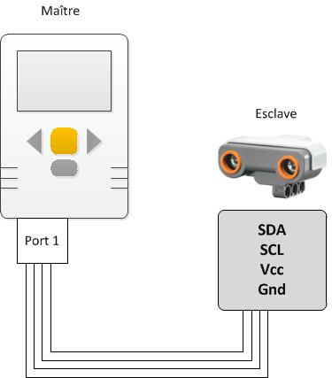
As the diagram above shows, four wires are needed for communication between the sensor and NXT brick (the NXT connection cables you use contain these four wires):
- Gnd (ground) is the reference potential
- Vcc supplies power to the sensor.
- SCL is the clock line, synchronizing the transaction between the two units.
- SDA is the data line, which is the line carrying the data exchanged between the two units.
These last two lines are the ones of interest to us for eavesdropping on the bus.
How does the I2C protocol work? The basic element is called a transaction. It begins with a START bit and ends with a STOP bit. Between these two bits is the actual communication itself. In master-slave mode, it is always the master that initiates a transaction. The first transaction will be for the master to write the I2C address of the sensor it is addressing to its connection bus. When you plug the NXT ultrasonic sensor directly into port 1 (for example), there is just one sensor and therefore no risk of contention. However, if you use a sensor multiplexer, you can plug more than one sensor into the same port and therefore, in this case, knowledge of the sensor’s proper I2C address is needed.
The image below shows just such an initial transaction, using the software supplied with the Saleae 100 MHz, 16-channel, USB logic analyzer. The upper line represents the SCL (clock) line potential and the lower line the SDA (data) line potential.
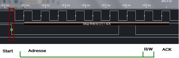
As the image above shows, a transaction begins with a START bit characterized by a falling edge in the data signal while the clock is in its high state. Then come 8 data bits. The first 6 bits are 0 (low SDA potential), the 7th is 1, and lastly the 8th is 0. All of which means that 0x02 has been written, i.e. the I2C address of the NXT ultrasonic sensor. As we said earlier, the first thing the master does is write the I2C address of the sensor with which it wants to communicate to the data bus. Lastly, the 8th bit is 0, indicating it is a write message.
The 9th bit is 0, this being the ACK (acknowledgement), i.e. the response from the sensor having the address 0x02, saying it is present and ready to respond to further requests from the NXT brick.
The image also shows one of the advantages of Saleae’s logic analyzer, which is that it writes out in full its interpretation of the data, like we have just done, by reading the potentials in the area between the two potential signals. It has written “Setup Write to [‘2’] + ACK”, which is exactly the transaction we have just described.
Now we know more about I2C, and have even introduced the Saleae logic analyzer user interface, let’s see how to physically build the circuit that produces this data.
Using the Saleae logic analyzer to eavesdrop on I2C communication
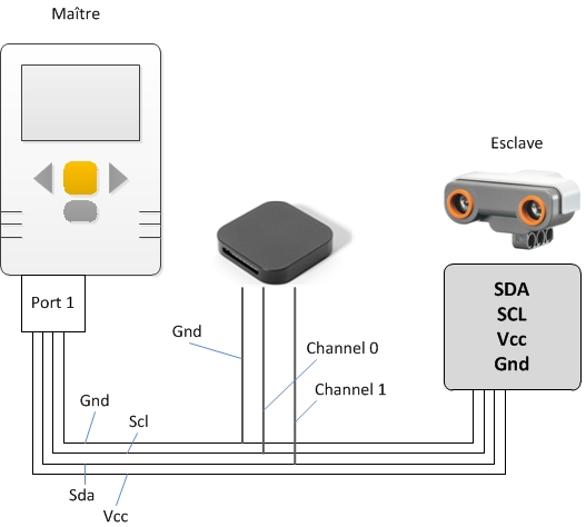
The diagram below shows the connection method for the Saleae logic analyzer so it can provide data on I2C communications between the Lego Mindstorms NXT brick and the Lego NXT ultrasonic sensor.
Once the circuit has been built, the software supplied with the Saleae logic analyzer has to be downloaded and installed. This software is available at http://www.saleae.com/downloads
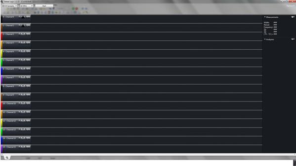
Once the software has been installed, plug the Saleae logic analyzer into your PC using the USB cable supplied. Run the software. The Saleae logic analyzer’s LED should then start flashing. The capture software’s user interface is as follows:
We will now configure the Saleae logic analyzer so that it carries out a clean I2C capture.
Firstly, let’s set the range of measured voltages. Go into Options/Logic16 Input Voltages and select “3.6V to 5V”.
Next, to improve the readability of measurements, go into Options/Display in Ascii and select “Ascii”.
Once that has been done, all that remains is to configure the software to run in I2C mode so it takes care of everything. To do that, go into Analyzers and select I2C mode.
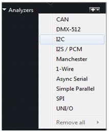
A new window should appear on your screen:
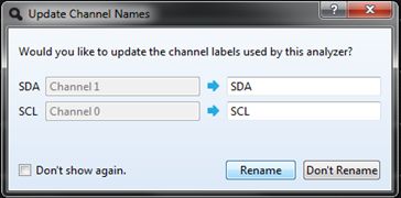
Take care to match up SDA and SCL to the correct channels – this obviously depends on your own cabling. Choose the name you want to give to your channels and then click on “Rename”.
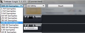
Now, we need to select the data acquisition time. As the image below shows, we are selecting 100 M samples at 16 MHz, which equates to 6.25 seconds of analysis. For I2C communications, a minimum of 2 MHz is advisable, but not necessarily needed. However, the faster we set it, the less likely we are to miss any data.
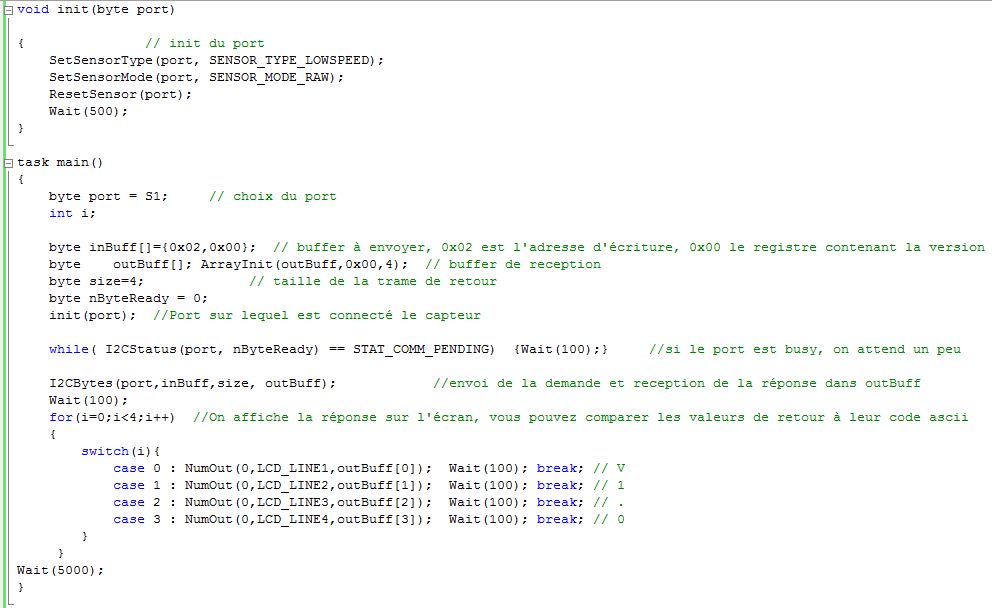
And that’s it, we are finally ready to test our logic analyzer. Well, more or less, since while we are ready to run a data acquisition exercise, what do we want to acquire? How do we ask the sensor to send us its version number? The following NXC code does this task. As a reminder, NXC is a C language for Lego Mindstorms NXT. The language used is unimportant here because the logic analyzer makes no assumptions about the type of program generating a communication, it just intercepts the message and analyses it. We could consequently have offered a program written in any language.
You can now click on “Start” in Saleae Logic, and launch the program on your brick. A pop-up window with a cursor then appears in the centre of your Saleae logic analyzer capture software screen. This means that the I2C transactions are being analyzed.
Once the analysis has finished, roll your mouse scroll wheel downwards to get the widest view of the full frame (the mouse scroll wheel zooms out, which is very useful). You should see a different area on your screen.
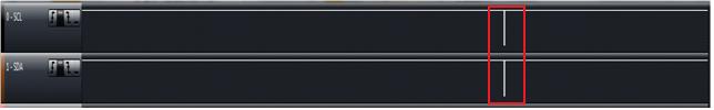
Position the mouse cursor on the area bordered in red and zoom in (roll the mouse wheel forwards). Your screen then looks like the image below:
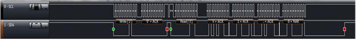
What you can see is the I2C transaction that took place between your Lego NXT brick and your ultrasonic sensor. Here, we can check that the data placed in inBuff was actually sent – and yes it was, because inBuff[0]=0x02, which is the ultrasonic sensor’s write address. inBuff[1] is transmitted next, to move to register 0, which is the one holding the sensor version. This frame is the result of using the NXC “I2CBytes” function; it sends the START signal (shown by the green circle), followed by inBuff, then it sends the STOP signal, shown by a red square in the capture.
Once this first transaction has been carried out, a second I2C transaction is initiated by sending a re-start signal (the second green circle), followed by the ultrasonic sensor’s read address (0x03). It then waits to receive in return a number of data items equal to the content of the size variable (4 in this case). It can be seen here that once the last data item has been received, the brick does not transmit an ACK, but a NAK, meaning the brick is no longer expecting anything from its slave. Transmission is ended by sending a STOP signal, i.e. a rising edge in the data line while the clock line is in its high state.
Conclusion
With this relatively straightforward example, we can clearly see the usefulness of a frame analyzer such as the Saleae logic analyzer, because even if some of you are not yet sure of its advantages, this small technological wonder will enable you to debug plenty of programs, since it performs a quick and easy check on the integrity of transactions between one or more of your controllers or actuators. Today, it is the companion of choice when learning the basics of electronic communications, partly because of its simple user interface, but mainly because of the service it provides, dissecting most electronic communication standards such as I2C, SPI, 1-Wire and many others for you, leaving you with a clear, readable, recordable and easily interpreted timeline.