Various techniques for positioning a mobile robot in a space
Every apprentice robotics engineer has built a robot that avoids obstacles by using touch sensors (of the ‘whiskers’ type) or infrared distance sensors.
However, for more sophisticated robots, that are to move around complex environments, higher-level sensors are needed. Various options are then open to the robot designer, depending on the type of mobile robot in question and its environment.
- Outdoor mobile robotics:
- GPS is a solution that is often used, although it lacks precision. Indoor GPS solutions are arriving on the market, notably with the help of Wifi hotspots.
- Indoor mobile robotics:
- With a navigation system using an external camera (arena with a vertical camera, for example);
- Using beacons (infra-red, laser, etc.) and signal triangulation;
- One or more cameras on board the robot (simple or stereoscopic camera, or indeed a camera with depth sensor such as the Microsoft Kinect), which requires data processing that may be difficult and intensive;
- Ultrasonic range finders (ultrasonic sonar) or infrared range finders;
- A laser range finder (also known as LIDAR).
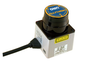
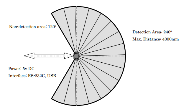
It is this last solution that we are going to examine here, basing our study on the most popular sensor amongst mobile robot builders, i.e. the Hokuyo laser range finder. This sensor is compact in size (50×50×70 mm), lightweight (160 g) and uses a 5V power supply (for smaller models such as URG-04-LX), which means it fits easily into mobile robots, even smaller ones. The various models offer ranges from 4 to 30 metres.
How a Hokuyo laser range finder works in robotics?
The principles behind laser range finders
A Hokuyo laser range finder estimates a distance by calculating phase differences. It emits a laser beam, i.e. a light wave at a particular frequency. This wave is described as monochromatic. The frequency used by the Hokuyo URG-04-LX laser range finder is 785 nm, on the boundary between visible light and infra-red. It is a Class 1 laser, meaning it poses no safety problems.
Background information - Laser classification:
- Class I: Harmless lasers, including products such as laser printers, CD players, and most situations where the laser transmitter is incorporated inside the product itself.
- Class II: Lasers with visible beams where the eye is protected by the blink reflex (e.g. bar code readers).
- Class III: Lasers where direct exposure to the eye is harmful either immediately (Class 3b) or after exposure longer than 0.25 seconds (Class 3a). Certain laser pointers fall into this category.
- Class IV: Lasers that are harmful to the eye (either viewed directly or reflected), which can cause injury and are also likely to cause fires. This category includes industrial lasers and those used in research.
This light wave moves in a straight line, rebounds from obstacles, and returns to the laser range finder. The range finder compares the wave sent and received and calculates the phase difference between the two. This phase difference is in fact proportional to the time taken by the laser to go from the sensor to the obstacle and back, and this time is itself proportional to the distance travelled.
The green and red waves have the same frequency, but are out of phase.
Laser technology is highly effective because the light wave is reflected from all solid surfaces with limited divergence, regardless of the nature of the obstacle.
Calculating phase delay with a laser range finder
If the emitted wave has the equation A.sin(w.t) (A being the amplitude and w the frequency), the reflected wave has the equation B.sin(w.(t -dt)) (the wave was emitted at the instant t –dt and its amplitude might have fallen if only partly reflected). Using a signal multiplier, we get:
A.B.(cos(W.dt) – cos(2.w.t – w.dt))/2
This signal is the difference between a constant signal (cos(W.dt)) and a high frequency signal (cos(2.w.t – w.dt)). A low-pass filter enables us to keep only the constant part, from which the travel time dt and therefore the distance, can be extracted.
Positioning on a plane using a laser range finder
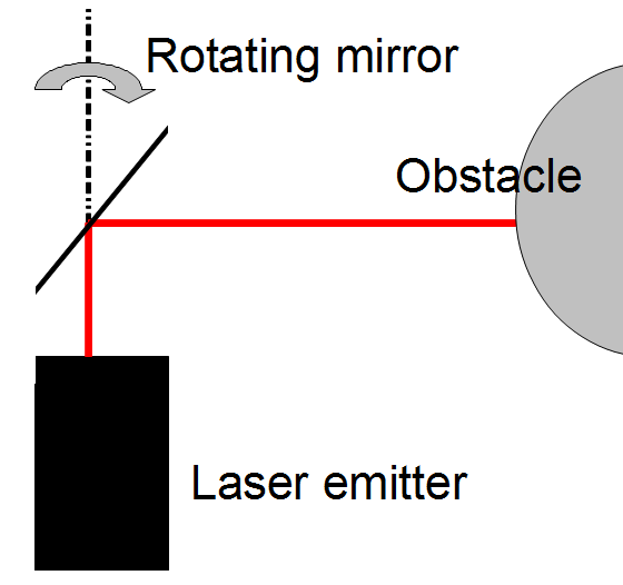
The principle described in the previous section works in one very specific direction. To take measurements over a plane, the sensor incorporates a small rotating mirror that shifts (by 0.36°) between each measurement. This movement is highly accurate but also very fast, and the Hokuyo URG-04-LX laser range finder needs just 100 ms for a 240° scan!
3D laser scanners use the same technique but with a mirror rotating on two axes.
Navigating around a space using a Hokuyo laser range finder
During each scan, the Hokuyo URG-04-LX laser range finder returns 683 distance measurements via its USB interface, equating to the 683 angles at which it takes measurements. These can be retrieved from a CSV file or directly in C or C++ code using the API (Application Programming Interface) supplied by Hokuyo.
The following is an example of range finder data:
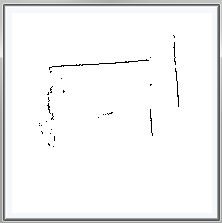
It is then relatively straightforward to convert this data into X and Y coordinates. Assuming the angle varies from -120° to 120° and the angle 0 corresponds to the Y axis, we obtain:
x = distance*sin(angle)
y = distance*cos(angle)
This data then needs to be interpreted to locate the position in the space.
If a map of the environment is available, an effort should be made to try to position any special points or landmarks, e.g. a door, gap in a wall, etc. The robot can then navigate its way around its environment, either by keeping the landmark in sight or by using encoders and a Kalman filter for instance.
If there is no previous map of the environment available, the robot needs to both map the area it is moving through and position itself on that map. This problem is called SLAM for Simultaneous Localisation And Mapping. A number of techniques exist to solve this problem, again including Kalman filters.
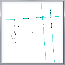
To reduce the amount of data to be processed, it can be helpful to pre-process it to extract shapes, and especially straight lines. The method most often used to do so is the Hough transform, which consists of calculating the equation of the straight line that passes through each pair of points. The coefficients for this straight line equation are added to a counter, which records how many times the same equation is calculated. The coefficients calculated the most often equate to many pairs of aligned points in the raw data.
Mobile robots using a Hokuyo laser range finder
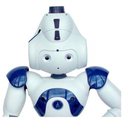
Among the robots using a Hokuyo range finder, it is worth mentioning the Khepera III robot fitted with its laser range finder extension and the laser-head version of the NAO humanoid robot.
Generation Robots (http://www.generationrobots.com)
All use and reproduction subject to explicit prior authorization.