This tutorial explains how you can use a serial protocol to control the mBot educational robot. You can adapt the code to make it more suitable for your project (or for use in RoboCup Jr events for example).
Robot teleoperation with an XBee chip offers 2 major advantages:
- It is much easier to set up and use compared to controlling a robot via WiFi or Bluetooth
- When used with the XBee module, you can recover data collected by the mBot’s various sensors (not possible with teleoperation from within the Makeblock mBot app)
How does our assembly work?
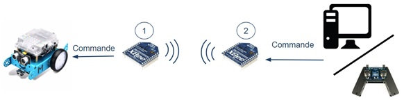
The system is composed of 2 XBee modules (one acts as a transmitter and the other as a receiver), an mBot educational robot and a module used to send the command.
In this tutorial, this last module will consist of an Arduino UNO board and a Grove joystick. (This system can be replaced with an ArbotiX Commander controller, which already includes an XBee chip!)
We will adapt the ArbotiX Commander controller code to the Arduino + Joystick system.
The data transmission frame used here consists of 8 bytes:
| Index (n° octet) | Description | Example |
|---|---|---|
| 0 | new packet (0xff) | 1111 1111 (dec: -1) |
| 1 | right joystick V | 0100 0000 (dec: 64) |
| 2 | right joystick H | 0000 0000 (dec: 0) |
| 3 | left joystick V | 0000 0000 (dec: 0) |
| 4 | left joystick H | 0000 0000 (dec: 0)/td> |
| 5 | buttons states | 0000 0000 (dec: 0) |
| 6 | extra | 0000 0000 (dec: 0) |
| 7 | security | 0000 0000 (dec: 0) |
Here, we sent decimal 64 on the second byte (index 1), which translates into 0100 0000 in binary.
In our Arduino Board + Joystick system, we will use just one joystick, so the only important data are those for byte 0 (new packet), 1 (right joystick V – Vertical), 2 (right joystick H – Horizontal) and 7 (security).
To translate the joystick values into motor commands, you’ll need the following mathematical formulas:
Right motor speed = right joystick V – right joystick H
Left motor speed = right joystick V + right joystick H
Using the packet sent earlier, this gives:
Right motor speed = 64 – 0 = 64
Left motor speed = 64 + 0 = 64
So the robot will move in a straight line.
Software, libraries and firmware resources required for this tutorial
Configuring XBee chips
You must configure each XBee chip using the
logiciel XCTU
. Follow the configuration steps below for each XBee chip.
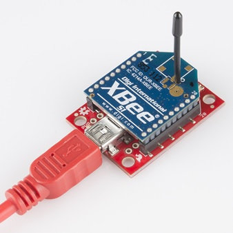
1. Connect your XBee chip to the computer using the XBee Explorer USB.
2. Connect to the XBee chip using the XCTU software. The video below explains how to do this.
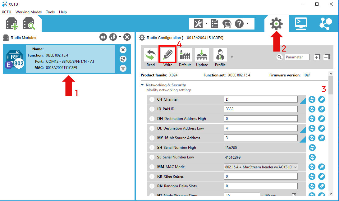
3. Then set the parameters for each XBee used (the table below will help you):
- Select the XBee on the left (1) and go to the configuration tab (2)
- Change the XBee ID (it must be unique) and the destination address (3)
-
Check its channel as well as the baud rate (it must be identical for all XBee modules required to communicate with each other)
(3) - Click on “Write” to save (4)
| XBee connected to | Channel | Destination address | Source address | Interface data rate |
|---|---|---|---|---|
| mBot | C | 2 | 1 | 38400 |
| USB PC | C | 1 | 2 | 38400 |
mBot robot connections
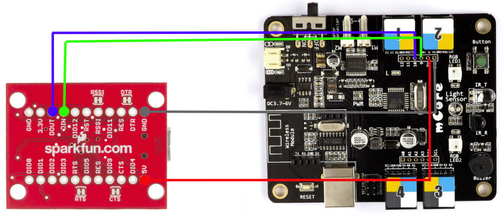
Below is a table summarising the different connections between the mBot robot microcontroller and the XBee Explorer USB.
| XBee | mBot |
|---|---|
| 5V | 5V |
| GND | GND |
| RX | 10 |
| TX | 9 |
Port 2 of the mBot robot is used by the XBee chip, so make sure you don’t connect anything to it!
Arduino connections
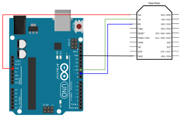
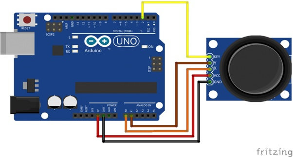
Below is a table summarising the different connections between the Arduino board, the XBee chip and the Grove joystick.
| XBee | Joystick | Arduino |
|---|---|---|
| Vcc | – | 3v3 |
| GND | GND | GND |
| RX | – | 9 |
| TX | – | 10 |
| – | Y | A1 |
| – | X | A0 |
| – | Key (unused) | – |
Installing the Arduino board firmware
- Connect your Arduino to the PC using a USB cable
- Open the Arduino_code.ino file (download link in the resources)
- Change the board type and the serial port according to what you are using
- Upload to the board (Ctrl + U)
Installing the mBot robot firmware
- Connect the mBot to the PC using a USB B cable
- Open the Arduino IDE and install the Makeblock library (Help)
- Open the Mbot_code.ino file (download link in the resources)
- From within the Arduino IDE, change the board type and select Tool -> Board -> Arduino Uno
- Upload to the board (Ctrl + U)
Once the firmware is correctly installed, restart the robot. And you’re done!