Graphical programming of the Scribbler 2 Robot (1/2)
This document provides an introduction to programming the Scribbler 2 robot using the Scribbler Program Maker, an entirely graphical programming language designed for the Scribbler 2 Robot.
The mobile Scribbler 2 Robot
First, let’s introduce the Scribbler 2 robot. As its name suggests, this is the second version of this robot first marketed in 2011. Scribbler 2 was designed by Parallax along with other programmable mobile robots. The table below gives a quick comparison of the main Parallax robots.
| Robot | Public | Microcontroller | Graphical programming |
Textual programming |
Difficulty | |
| Boe-Bot | 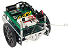 |
Secondary school & University | Basic Stamp 2 | No | Yes | ++ |
| Scribbler 2 | 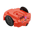 |
Secondary schools | Propeller | Yes | Yes | + |
| SumoBot | Secondary school & University | Basic Stamp 2 | No | Yes | ++ | |
| StingRay | 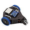 |
Secondary school & University | Propeller | No | Yes | ++ |
Click on the name or picture of each robot for a detailed description of its functional and technical features.
The Scribbler 2 Robot does not require any construction and can be used immediately.
Scribbler 2 is a robot that is mobile (meaning it can move), autonomous (meaning that it can make its own decisions thanks to its embedded microcontroller and its various sensors, which allow it to perceive its environment) and programmable (meaning you can create and modify the program rendering it autonomous).
Mobile robotics is a very specific branch of robotics that is widely taught today. Mobile robots are differentiated by the number and diversity of their embedded sensors; the more sensors and the more different sensors a robot has, the more complete and accurate a “vision” of its immediate surroundings it will have. The Scribbler 2 Robot has three light sensors, two line trackers, three infrared distance sensors and a jamming detection sensor (sensor that indicates if the robot is jammed against an obstacle and its wheels are spinning). The Scribbler 2 Robot is well equipped in terms of sensors, which makes it particularly suitable for teaching robotics.
The main feature of version 2 of Scribbler is its microcontroller, the Propeller. This is a multicore Parallax microcontroller, meaning that it can effectively run tasks in parallel, which is essential for a robot. The Propeller is also the microcontroller in the Stingray robot.
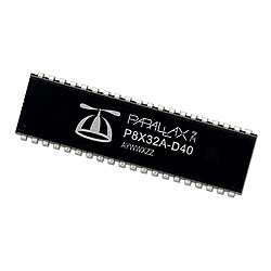
The Propeller microcontroller
For a more detailed description of the Scribbler 2 Robot, go to http://www.generationrobots.com/en/401387-scribbler-2-robot-serial-parallax.html
Programming the Scribbler 2 Robot
The Propeller can be programmed using SPIN language, a language created by Parallax specifically for this microcontroller. SPIN can also be used to program the Scribbler 2. In addition, since the Scribbler 2 is aimed mainly at young secondary school students, Parallax offers a graphical programming software tool called Scribbler Program Maker. This programming software can be downloaded free of charge on the Parallax web site at http://www.parallax.com/Portals/0/Downloads/docs/prod/robo/scribbler2/S2GraphicalUserInterfacev1.3.1.zip
In this article, we are going to briefly describe this software and then create an obstacle avoidance program. This software does not require any particular programming skills.
Installing the Scribbler 2 Robot programming software
First, download the ZIP file and unzip it in the destination of your choice. Then double-click on the executable file contained in the unzipped directory, and follow the installation instructions. The software version may be slightly different, but the procedure is the same.
You don’t need to have the robot to test the software, so give it a go!
Introduction to Scribbler Program Maker
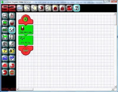
The Scribbler Program Maker interface looks like this:
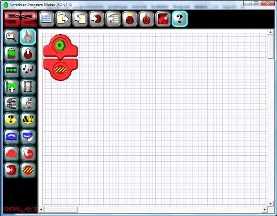
Scribbler Program Maker, the graphical programming software application for the Scribbler 2 Robot
The programming principle is simple. You simply click on one of the icons in the side bar on the left and drag the corresponding tile to drop it between the tile marking the start of the program (a green gear wheel) and the tile marking the end of the program (a yellow and black striped panel).
To understand how it works, click on the icon showing a Scribbler 2 with a white arrow on it (second icon from the top of the right-hand column). This icon allows you to control the robot’s movements.
Once clicked on, the icon is outlined in light blue. Place your mouse between the program start and finish tiles. A grey bar with inward-pointing arrows at each end will then appear, as shown in the following picture.
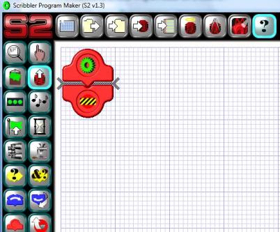
Positioning a program tile
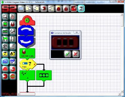
When the grey bar appears, click once and the tile selected on the left will appear on the programming sheet between the program start and finish tiles where the grey bar is. A small control box opens allowing you to configure the settings of the motion tile you have just dropped.
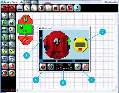
Motion tile settings window
The figure above shows this settings window.
- This cursor is used to determine the power of the motors turning the wheels. The higher the power (in either direction), the quicker the robot moves. When the cursor is in the middle, the power is at zero and the robot is stopped. This cursor is a measurement of the mean power. You can also configure just one of the motors by moving the red or green arrow, which will move the cursor and make the robot turn.
- The stopwatch shows how long the movement is to last. Click on it to activate it. It is graduated in seconds and can be configured for up to a maximum of 5 seconds. If it stays grey, the movement is repeated indefinitely until the program meets a new motion tile or until the end of the program. You will notice that setting the stopwatch on the graphical part also makes the cursor move below. They both manage the same data.
- These are counters that show the values controlled by manipulating the arrows or the graphical stopwatch. The colour corresponds to the variable controlled.
- These are the validation button (green tick) and the cancellation button (red cross). These two buttons close the settings window.
- This is the selector button, allowing you to pre-position the values relative to the power of the motor to carry out one of the standardised movements.
In our example, let’s set the two motors and the stopwatch to maximum. The robot will thus move forward at top speed in a straight line for 5 seconds.
Let’s now repeat the same operation, adding the sound tile represented by musical notes in the toolbar.
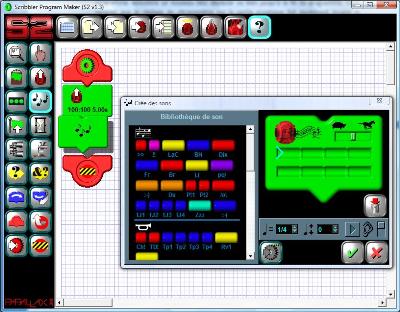
Inserting the sound tile
This tile allows you to make the robot play a sound or a tune, which is very useful for marking the steps in a program. The settings window is divided in two vertically. On the left, you have a sounds and tunes library. On the right, you have your tray on which you are going to place your sounds and tunes. The robot will then play them as a sequence. To add a sound to your tray, click on a coloured box on the left. It will automatically appear on the right. You can listen to the result directly by clicking on the Play button (a triangle pointing to the right). To delete a sound from your tray, click on the dustbin button.
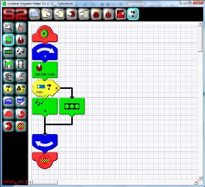
Select your tunes and validate. The structure of the program should now look like this:
Finished program
We are now going to run the program. To do this, you must connect your robot to your PC using the USB cable and the USB-Serial adaptor sold with your robot. Be aware that the first time you connect it, you must first install the USB-Serial driver found on the Parallax website at http://www.parallax.com/usbdrivers by connecting only the USB-Serial adaptor to your PC using the cable. Only then should you connect your robot.
Switch on your robot and press on the “Copy the program to Scribbler” button, which is the 4th button from the left in the horizontal toolbar at the top.
A small window marked “uploading” will open while the program is being transferred to your robot. If the robot is not switched on or is not correctly connected, in short, if your PC cannot find the robot, a window opens with the statement “No connection could be made to your Scribbler”. Check that your robot is on and connected, and start again.
If your robot is correctly connected, a window saying “Upload successful” will be displayed and your program will start immediately.
And that’s all there is to it – you have created your first program!
In the remainder of this article, we are going to look at the main tiles available.
Modifying the settings of a tile
Before finding out about other functional tiles, let’s see how to modify a tile that has been configured, as this can be very useful.
To do this, click on the motion tile. It will “float” above the interface, indicating that it has been selected.
Right-click and a small Edit window will open, as shown in the picture below.
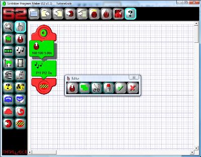
Functional tile modification window
There are six buttons in this window:
- The first button is specific to the selected tile. In our example, if you click on it the Edit window closes and the tile settings window opens.
- The second button allows you to copy the selected tile. Once you have clicked on this button, close the Edit window using the second to last button and then place your cursor at the place on your diagram where you wish to paste the tile (remember, the grey bar will appear) and then use the paste button located in the tiles bar on the left (the second tile from the top in the first column, with the green paperweight on it). Hey presto – your tile is copied!
- The third button is the Cut button. It works like the previous one, but cuts instead of pasting.
- The Dustbin button is the fourth button. It is used to delete the current tile. Simply click and then select the 5th button to close the Edit window and your tile will be deleted.
- The 5th button allows you to validate choices made and to close the Edit window.
- The 6th and final button allows you to reject choices made and to close the Edit window.
You now know how to correct errors, which is pretty good, and can prove very useful.
Conditions
All programs integrate tests, also known as conditions. In robotics, for example, the value of a sensor is tested in order to make a decision.
Let’s go back to our previous program, and instead of making your Scribbler robot play a nice tune after a hectic 5-second dash, let’s carry out a light test. If the light is strong enough, it will play a tune. If it is not strong enough, it won’t.
We will insert an if-then-else tile between the two previous tiles. The if-then-else tile is the yellow tile with a large question mark. The tile looks different from the two previous tiles. We will come back to this later. Let’s spend a bit of time looking at the settings window.
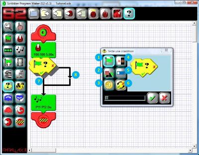
If-then-else tile settings window
Once again, there are six buttons in the settings window:
- Used to test if a flag is raised or not. As we will see later, a flag is a variable that can take two values (seasoned programmers will talk of Booleans), i.e. raised or not raised. This makes it possible to test a previously defined status.
- Used to test if an obstacle is detected by the infrared sensors and, if it is, where it is located (e.g. in the front, on the left, on the right). It can also be used to detect wheel spin, i.e. when the wheels are turning but the robot is stuck.
- Used to test the value of a virtual coin-toss test, in other words a random test.
- Interrogates the infrared line tracking sensors located under the robot. These sensors are used to track a line.
- Interrogates the light sensors. There are 12 conditions that can be tested:
- The value of one of the three sensors is at least X (where X ranges from 0, representing black, to 255, representing the greatest measurable light intensity)
- The value of one of the three sensors is the most luminous of the three by at least X
- The value of one of the three sensors is the least luminous of the three by at least X
- The mean, the maximum and the minimum is at least X
- The last button is used to reverse the true or false conditions on the if-then-else tile (mainly for the presentation).
Select the light test you wish to perform. We recommend that you select an unambiguous test, such as the total absence of light (e.g. if you put your fingers on one of the light sensors).
Now you just need to move the tile that plays the sound so that it only plays the sound if the condition is met or not met (it’s up to you). To do this, copy the sound tile that is already in place and paste it under the if-then-else tile. In the previous picture, the number 7 represents a condition that is met, as it is located under the green tick on the if-then-else tile. The number 8 represents a condition that is not met, as it is on the path of the black arrow situated after the red cross on the if-then-else tile.
To be sure it is working properly, you can insert two different actions dependent on the result of the test. The following picture shows the case where the robot plays a sound if its environment is light enough, and its three LEDs come on simultaneously if the environment is not light enough (e.g. if you cover its front left light sensors with your finger).
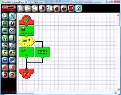
Mise en œuvre d'une condition simple
Loops
We can’t end this initial introduction without spending a bit of time looking at loops. Together with conditions, these are the most used programming structures. A loop is used to repeat a sequence of actions (whether determined or not) a certain number of times.
Let’s go back to the code shown in the previous picture and imagine we want the entire program to repeat four times, so that we have time to test the program. A loop type tile must therefore be inserted around our four functional tiles.
To do this, select the start of loop tile, which is the 7th tile from the top in the left-hand column of functional tiles. It is blue with a curved arrow pointing to the right. Place this tile right at the start of your program, directly under the red start tile. A loop settings window opens, as it does each time you drop a functional tile on your diagram.
Loop tile settings window
The settings window is shown as a counter. This counter is disabled by default. If you click on the validation button without modifying the counter, no number of repetitions will be defined for the loop, which corresponds to the program being repeated to infinity. If, on the other hand, you select a number in the counter and click on the validation button, the number of times the loop is repeated will be defined, which means the program will stop of its own accord after X repetitions. In our example, we have set the counter to four.
Now, we just need to copy the program’s functional tiles and paste them in the Loop tile. To do this, click on the finger-shaped tile at the top left, which transforms your cursor back to selection mode, and click successively on the motion tile and the if-then-else tile. You will notice that when you click on the if-then-else tile, the tiles located below in conditions met and conditions not met are also selected. All the tiles depending on a given tile are automatically selected. Now perform the cut/paste operation as we saw earlier.
Program finalised with 4 repetitions
Conclusion
In this article, we introduced the Scribbler 2 graphical programming interface. We saw the linear flow programming concept, how to act on the robot’s movements, how to interrogate its sensors, how to manage a condition and, finally, how to perform repetitions. These basic concepts will allow you to produce many simple types of behaviour, which is ideal for novice programmers, particularly younger ones. You don’t need to know anything about programming and the visual interface is very easy to understand.
In a second article, we will see how we can take this a bit further, and focus more specifically on code modularisation and the management of parallel tasks – which is what the Propeller microcontroller was actually designed for.
Generation Robots (http://www.generationrobots.co.uk)
all use and reproduction subject to explicit prior authorization.