Dynamixel controllers
The controllers (or control boards) allow you to control the Dynamixel servos that bring your robotics creations to life!. A controller in a robot plays the role of the brain, and they will allow you to program them. There are different controllers based on the usage and specifications.


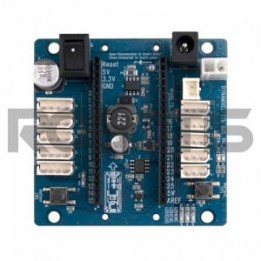

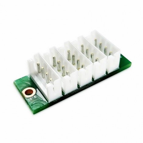
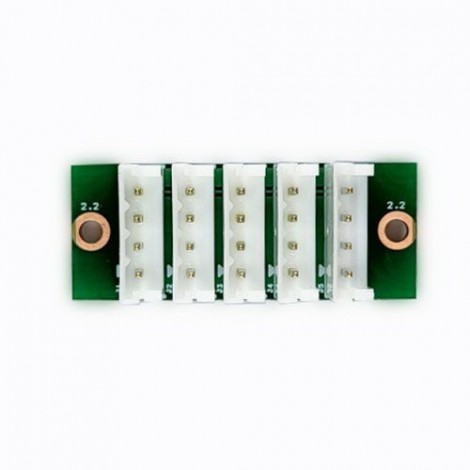
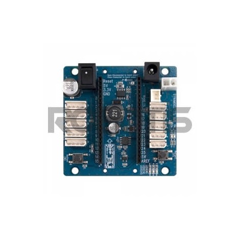
The 4P JST Expansion Board is an extension board that allows you to add additional features to your robot.
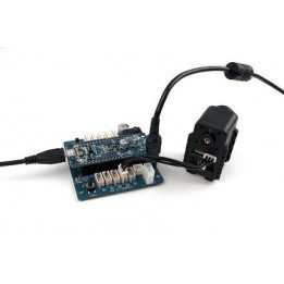
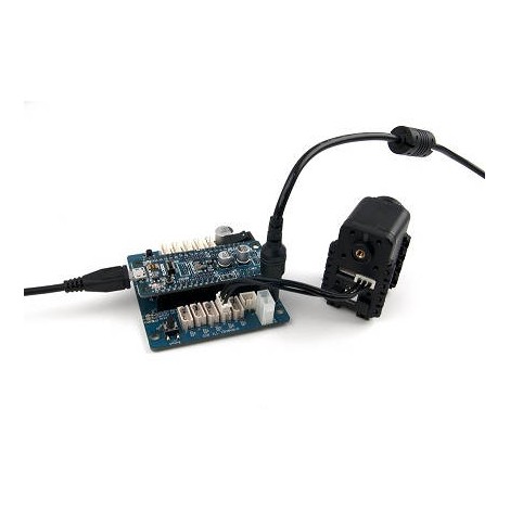
This Dynamixel servo controller offers multiple functions for fully operating your robot in navigation mode. It includes various sensors and enough connection ports to add several devices.
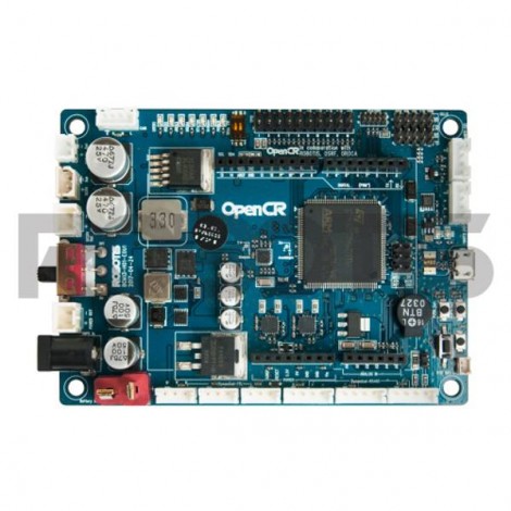

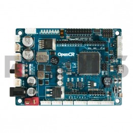
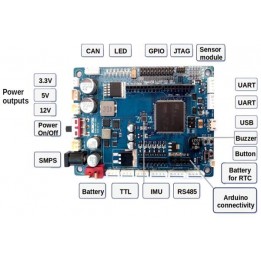
This open-source controller would be the ideal choice for your TurtleBot3 robot; it is an ROS controller equipped with an ARM Cortex-M7 processor capable of accommodating your Dynamixel servos and many other modules!
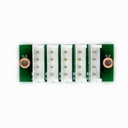
The OpenCM 485 Expansion Board connects to your OpenCM9.04 Controller so you can benefit from additional Dynamixel ports.
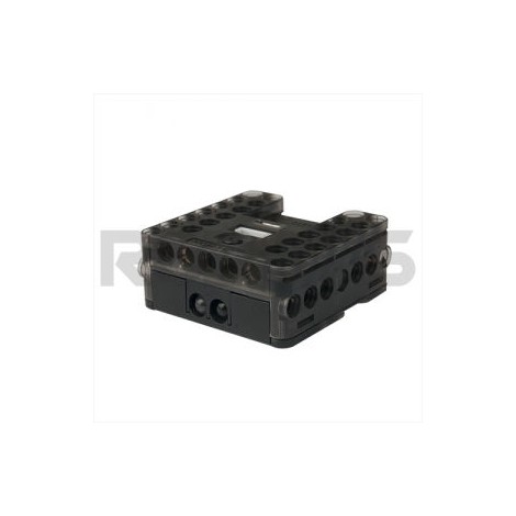
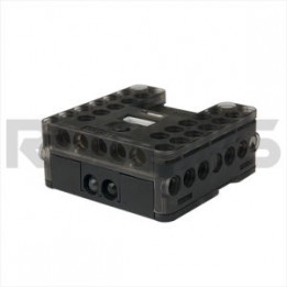
The CM-150 Controller is used for programming robotics kits like the Robotis Dream Level 2. It will allow you to connect numerous components, for example sensors, gearmotors and LED modules.
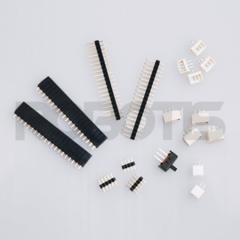
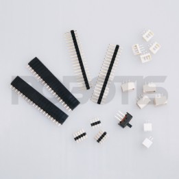
Make your OpenCM9.04-A control board for Dynamixel servomotors complete with this accessory set.

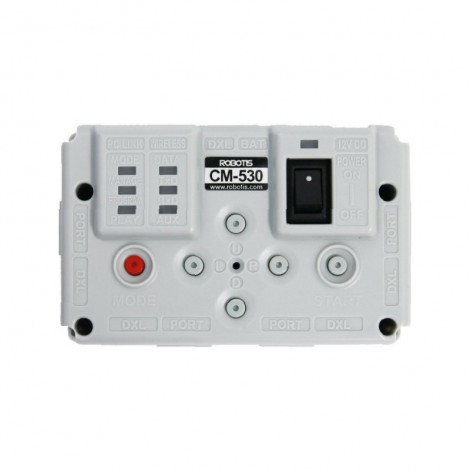
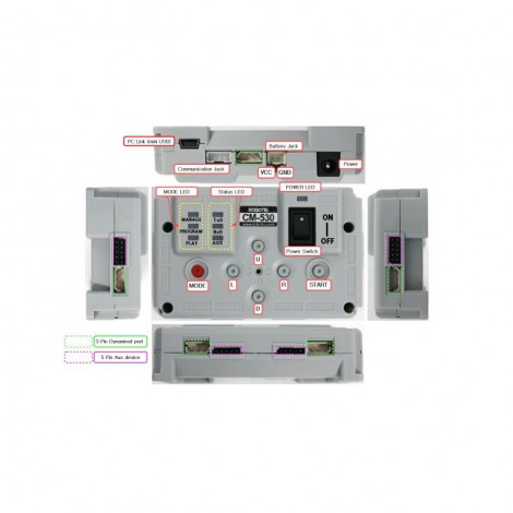
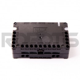
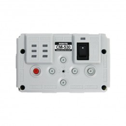
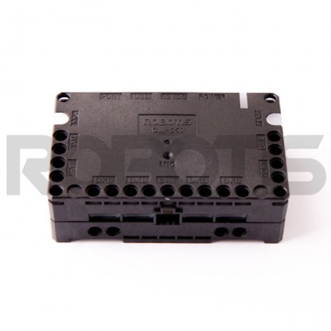
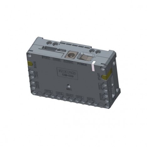
The CM-530 main controller drives your Dynamixel servomotors AX and MX. It carries a ARM Cortex STM32F103RE microcontroller and is programmed in USB with the RoboPlus software.